Belt cover has been removed for illustrative purposes only.
Do not operate a Surface Planer in this configuration.
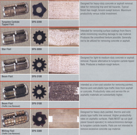
Surface planers are ideal for removing trip-and-fall hazards, stripping
thick, high tensile floor coatings or profiling any surface for a new
coating. Specially designed carbide flails can effectively remove
thermo and cold plastic type markings from streets and industrial floors.
The SP8 Series II surface planers make your surface preparation seem plane
easy.
Why
Is The Drum In Front Of The Wheels?
To maximize productivity and service life, it is essential for the wheels,
and not the drum, to support the weight of the surface planer during operation.
Positioning the drum in front of the wheels offers several operational
advantages. For traffic line or surface coating removal, the front
position allows the drum to produce a more uniform and consistent finish.
Compare the differences between a front-mounted and center-mounted lawn mower
deck. With the drum positioned in front of the wheels, there is
less tendency to "scalp" the surface. (See Drum Position).
When removing trip-and fall hazards from a sidewalk, the advantages are
even more evident. The front position allows the drum to be positioned
on the lower surface, perpendicular to the misalignment. Rough cutting
the material quickly establishes the grade line with less physical effort.
Once the bulk of the misalignment has been removed, the surface planer
can be repositioned parallel to the grade to remove additional material
for more gradual blending. If a smoother final finish is required,
less aggressive flails can be utilized.
|
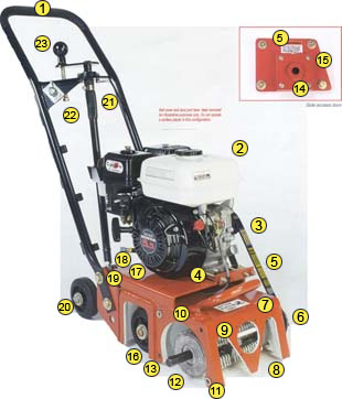
1. Comfortable operator handle .
Full width, tubular design maximizes operator leverage and control.
anti-skip, polyurethane coating helps maximize helps maximize productivity
and minimize fatigue.
2. Choice of power sources.
5 or (3.7 k.W) category gasoline: 5 hp (3.7 kW) electric , domestic
or foreign voltage operation and 8.5 hp (6.3 kW) pneumatic.
3. Twin V-belt drive system.
Absorbs and minimizes shock-loading back to power source. Twin-belt
configuration provides extended service life and redundancy.
4. Dual V-belt tension adjustment.
Properly aligns engine and maintains belt tension to factory specifications.
Proper tension increases belt and bearing service life.
5. External grease fitting.
Facilitates greasing bearings at regular intervals to maximize service
life.
6. Belt Cover (not pictured).
Heavy-guage, welded, sheet metal cover helps protect drive system
from external damage. Bottom guard configuration helps minimize
material ingestion into V-belt drive system.
7. Carry handle.
Comfortable and functional when loading or unloading.
8. Standard 3" diameter dust port (not pictured).
Connects directly to vacuum systems. Larger size helps minimize
static pressure loss while increasing vacuum system performance.
Front location allows vacuum hose to better clear and remain free of machine
during operation.
9. Dual port deflector.
Helps minimize potential for a damaged flail to exit the dust port.
10. Water-mist dust-control fitting.
Allows installation of a valve and water source as an alternative
method for dust control.
11. Access -door alignment pins.
Precision mounting configuration minimizes machining and bearing runout
tolerances. Heat treated to maximize service life.
12. Full-length hexagon driveshaft.
Hexagon shape maximizes driveshaft and drum contact area. Helps
disperse impulse forces over a wider surface area to minimize wear.
Manufacturing tolerances speed drum installation yet minimize "hour glass"
wear on both driveshaft and drum. Heat treated to maximize service
life.
13. Drum positioned in front of wheels.
Increases machine stability by reducing recoil forces. Provides
greater uniformity and consistency when removing surface coatings.
14. Replaceable outboard bearing bushing.
Precision-broached hexagon shaped bushing can be quickly field replaced.
Heat treated to maximize service life.
15. Side access door.
Allows drum to be quickly changed without tipping machine forward or backward.
16. Replaceable forward casters and axle.
Worn components can be field replaced individually or together without
realignment difficulty.
17. Replaceable wear bushings in all pivot areas.
Heat treated, full-length bushings increase service life in high-wear
areas.
18. Convenient oil drain.
Promotes proper oil change intervals on engine powered units.
19. High-capacity automotive-type ball joint.
Heat treated to reduce linkage rod wear.
20.
Replaceable rear casters and axle.
Worn components can be field replaced individually or together without
realignment difficulty.
21.
Screw-type drum height control system.
Worn components can be field replaced individually or together without
realignment difficulty.
22.
Remote located engine ON/OFF ignition switch.
Connects directly to engine-mounted ON/OFF ignition switch.
23.
Drum-height control lever.
Operator input controls drum height during operation. One complete revolution produces
approximately 1/16 inch (1.6mm) vertical height movement.
|